Banshee Model One
This section is for the Milspec information and how to go from the mil spec to a derivative work based on the Copy Left
domain parts that are Milspec. I am following the stoner M-16, AR-15 model as closely as makes sense. Most people
know that once the design is paid once and the patent office signs off on it being mil spec it is much like public domain,
where you don't have to worry about who you have to pay for the design and you don't have to worry about using a
standard bolt that is required for the design to work as long as you can build a physical product or include it as part of
something that adds value and you are not making money off the actual design but a derviative work it is the same no
cost worry, as it has already been payed for. In this case the money has not been cleared but honestly that is not a
designer working off the design's problem unless they are fighting the design being mil spec or fighting the payment
since the contract has been in force since november of nineteen ninty seven.
This section is for the Milspec information and how to go from the mil spec to a derivative work based on the Copy Left
domain parts that are Milspec. I am following the stoner M-16, AR-15 model as closely as possible.
Going from the milspec aerofoil or aeroframe, the parts need to be designed so that if people have different ideas for
forking the body cladding, the interior metal runners that the cladding is attached to, the beams that the cladding is
attached to. The truss beams attach to the structual beams. The interior mechinal parts and surfaces attach to the
truss beams.
So I built the aerofoil concept from looking at cigar boats, sea planes, a dozen military jets and having fligth hours in a
T-38 Trainer, F-104 starfire, and F-16cj block 52. Landing all of those really is not fun. I have driven cigar boats, bostin
whalers, and a sailed a couple yatches. Those going over a wave hard hurts but a really hot aerospace craft coming
and trying to land on run way just seems like a bad idea. The issue is what if it needs to go right back out? So I started
looking at really fast cars and boats. Then I realized I plan to run air through the intakes to the turbines. So if the aerofoil
is sitting in the water with the intakes able to open and close I can simply have it suck in water and air, creating the
rooster tail of a cigar boat and use the wing body to creat just enough lift that the bottom of the aerofoil acts like a cigar
boat, until it is air born or into the water depending on if it is speeding up or slowing down.
So that means that the basic design has to be public domain and then let companies build upon the basic concept.
This covers things like contouring and wing body shape because the higher accerations require more structure not less
weight. The design I built has far more thrust than any combination of material design I can find commerically avalible.
The rib on the spine of the aerofoil was needed for a craft filled with vaccuum since the water vapor hitting the crew's
body is half the gee force felt.
So I think the most practical design is bolted but I might be wrong. So I use the word attach. So a design could build on
it by welding or bolting or gluing or whatever a company thinks can work, but if the design practical version fails to meet
minium levels of safety then it is not milspec. The United States Department of defense is going to set the final level of
what is actually required by the spec I am just covering what I transfered to Mil Spec a type of Copy Left.
So the wire color coding is the basic design if more wires are needed they have to be visibily different than the wires
listed. What goes down which wire that can be set later but the idea is to unified the wire color coding to the point it can
be submited as a request for comments. This is so that if a section of wiring fails in space, it can be unattached at the
bulkhead sections, and the same coloring wiring matched in place and have it work as it was before the wiring section
fails. This is an eight section wiring design that is visiblily different in low lighting. There is a couple other variations of
eight wire but none of them are the same. On of the worst things that can happen is running across a wire and having
no idea where or what it goes to when fixing an airframe and having to remove all the outer panels to figure out what
componets it goes to. What makes sense to me might not make sense across the board but if most designs are built
with eight wires that are connected through the bulheads via a wire connector of some kind, that attached eight different
types of wires the practical models that become compeditors for the United States Armed Services YF-37 variants. The
design requires compressed gas that needs to be clearly set as to what a canister contains. Right now hospitals are the
closest to uniform. Everyone seems to agree that a dark green color is oxygen, a bright red color is hydrogen, and
medical air is yellow. I would include enamling any intake runs that come form the outside of the air frame to be yellow
inside so that if an intake run is punctured you know that it has to be patched before re-entry. If using tempered glass
rods to make sure they don't break as fiber optic cables you still use eight rods and use a push in latch that locks back
like a bnc connector.
Wire Color Code
A1 Blue - White Strip
A2 Red - White Strip
A3 Blue
A4 Red
A5 Green - Magenta Strip
A6 Yellow - Magenta Strip
A7 Green
A8 Yellow
Canister Color Code
Medical Air - Yellow
Oxygen - Green
Hydrogen - Red
All rights reserved. Copy right 1992-2017. That means in simple terms that people's trademarks are there own though none are in this story but new content.
In the model design I used a naming convention that much like port and starboard is there so that instead of trying to figure out what country the part is from, simply labeling parts on the actual part based on North East South and West. Sailors looked to the north star as the easiest find since it was the brightest star, thus sitting in the helm you are looking forward so the furtest point forward the helm is north, thus looking forward anything to your right is east and anything to the left is west, looking south the reverse applies. So the west is always the west side of the aerofoil and the east side is always the east side. This sounds like extra to most people but in north america port is the west because you sailed out from the east coast and back to port by sailing west. In Europe sailing west meant going to sea and sailing east meant sailing home or to the far east.
I created a short hand that may be useful
North 12XX
West 09XX
South 06XX
East 03XX
Up XX24
Equal XX00
Down XX18
Fore 12
Aft 06
Port 09 | 03
Starboard 03 | 09
Command C--
Helm A1X
Quarter Q2X
Systems S3X
Nav N4X
GunnerWest GWX
GunnerEast GEX
Where command is followed by the chair designation and the other chairs are followed by an X. Meaning that with Captain who is a Pilot there part designations would be CA1. A QuarterMaster's parts who was a captain would be CQ2. A pilot in a non captains helm would use A1X.
Structual Element SEXXXX
Moving Part MPXXXX GO|NOGO parts
Electical Element EEXXXX
Pnuematic Element PNXXXX
Biohazard Element BHXXXX Parts exposed NBC elements
Hatch HDXXXX
Chair SCXXXX
Light ILXXXX
Ladder LSXXXX
Outer OTB
Inner ITB
So the first NWSE is the side of the craft, working your way inward. The second is if there are two elements the one to the left being the west element with respects to looking fore. If it is higher than it is twelve higher and if lower six higher and zero if not higher or lower.
WestStarBoardGunnerHatchOuterLadder_Step001
0900-03-GWX-MP0001-OTB-SE0001-LS0001_Step001
The last part step001 means that you have a top step a load bearing step then a first step. So it is the step going down from the top of the ladder that is not the top step or the load bearing step. The top step in a ship is a walkway that is at the top of a stair, and the load bearing step has extra support as it is stood on to open hatches, and has extra force applied against it.
- Chapter Eight
- Chapter Nine
- Chapter Ten
- Chapter Eleven
- Concept for Armed Services Commitee
- Banshee YF37 Mil Spec Draft
- Service on Retainer & Parts on Delivery
The concept is to have the cladding be built to attach down to metal runners so that they snap in place from the back and have the wind hit a uniform surface but in practice it may work better to simply have them attached down next to each other instead of sliding forward and being bolted down. The most important part to consider is the design needs to force the fluid body it is moving through be it water vapor or even freezing rain away from the lifting body and then fall back to the plume created by the heated fluid or plasma behind the afterburn or exit nozzle. The cladding has to deal with expansion and compression, since the pressure has to change. One thing I noticed is in looking at volcanos the granite or silocone iron alloys tend to not expand or contract much at all so drilling out granit cladding might work. Another option is high speed steel with signifacant amounts of cobalt to slow down the impact of hot and cold tempature extremes. Some companies my find that making it a foot thick with aircraft alimium works best and others may have a couple inch thick layer of M42 or M48. The idea is that cladding is able to deal with the contoured surfaces to slip stream air across it and deflect it away form the aerofoil, so that when the aerofoil goes from hard vaccum tempatures to warm water vapor it does not end coated in ice and drops like rock out of the sky. With the propellent exhausting water vapor this is really important in a cross draft wind.
The propulsion system is a thorium salt reduction via a isotope laced hard water. Thorium salt reactors use florirde to pull off electrons at an even rate and electrify the water with ions which can be collected via copper coils. Due to the pressures involded of using pressized hydrogen and oxygen and combusting them together with what amounts to water purfication tablets to create something simalar to the water in a reactor, when it is sprayed into a fluid soltion that contains un used thorium crystals the ions are pulled off by coils made of tempered steel coated or electroplated in copper grounded into power lines (which color code they will be is up to which of the eight color codes above is used for power). The water when electricfied is ciruclated through the reactor chamber as gas is bleed off at the back as the electricaity decomposes the hard water back into oxygen and hydrogen. The gas as it is bleed off is vented into the intake combustion chambers as the electric current also turns the fans which are very heavy magneticlly spun bearlingless fans. The west and east sides have to spin towards each other as the incoming pressurized gas spins them faster pulling the water over the coils much faster. The air pressure leaving the bleed off vents needs to be as strong as possible as the faster the fans spin the greater the speed of the water over the coil the more current that is pulled off them. The power lines need to run up to anoid style capactor wire. Pulling current off them to run the turbines and run the power system likely requires a control board with computer capictors pulling off leads attached to the capasicatend wire loops. A magnetic amrature like the original electric powered sewing machines that first gasoline engine was built off of could be used to controll the speed of the turbines or turn them with crankshaft. The most power effiencent is a ramm air turbine that takes pressuirezed air and mixes it with in from the intakes in atmosphere and from pressurzied gas canisters in vacuum. Being able to spray hydrogen and oxygen or medical air into something of design simalar to a jet fuel based denator driven turbine means that as long as the all the connectors match up different manufactures could build different variations on the turbines. The pattern of the turbines and the ability to speed up and slow down them independantly is large part of the abilty to steer the aerofoil. The secondary control is the ruddars or lifting surfaces attached to the rear of the wing body which are designed to have atmospheric control with normal air flow and secondary vents pointing at them to spin them along the main beams axial. Think a paper airplane on a string that can spin along the axial from tail to nose. One note of caution. NOS sublimanted can go whoom or boom. Thin pipes metal pipes can freeze
and crack under latteral sheering force. There was an old mail order rocket engine you could buy like goddards peroxide and liquid nitrogen model
engine. It vaporizes about a thousand feet off the ground. I assumed everyone would start there but there are two alternate designs to the ones here
that used thin pipes so look at the design of canisters and remember glass over four inches thick does not transfer heat in either direction.
Clearly having seen some silly montages people are going to have to at least build a model rocket first. I built ten that gave me a bad sun
burn that nearly got me in a serious trouble with the USAF. The STL_ATF at least gives those with a large enough scale cnc setup
a file they can take into a CNC program and build a sheet metal concept at least four inches thick. To go through entry and re-entry via
space you need at least four inches of quartz or the equivalent space tile. The design calls for the equivalent of dense iron alloys with
quartz melted then poured onto the metal as a candy coating four inches thick.
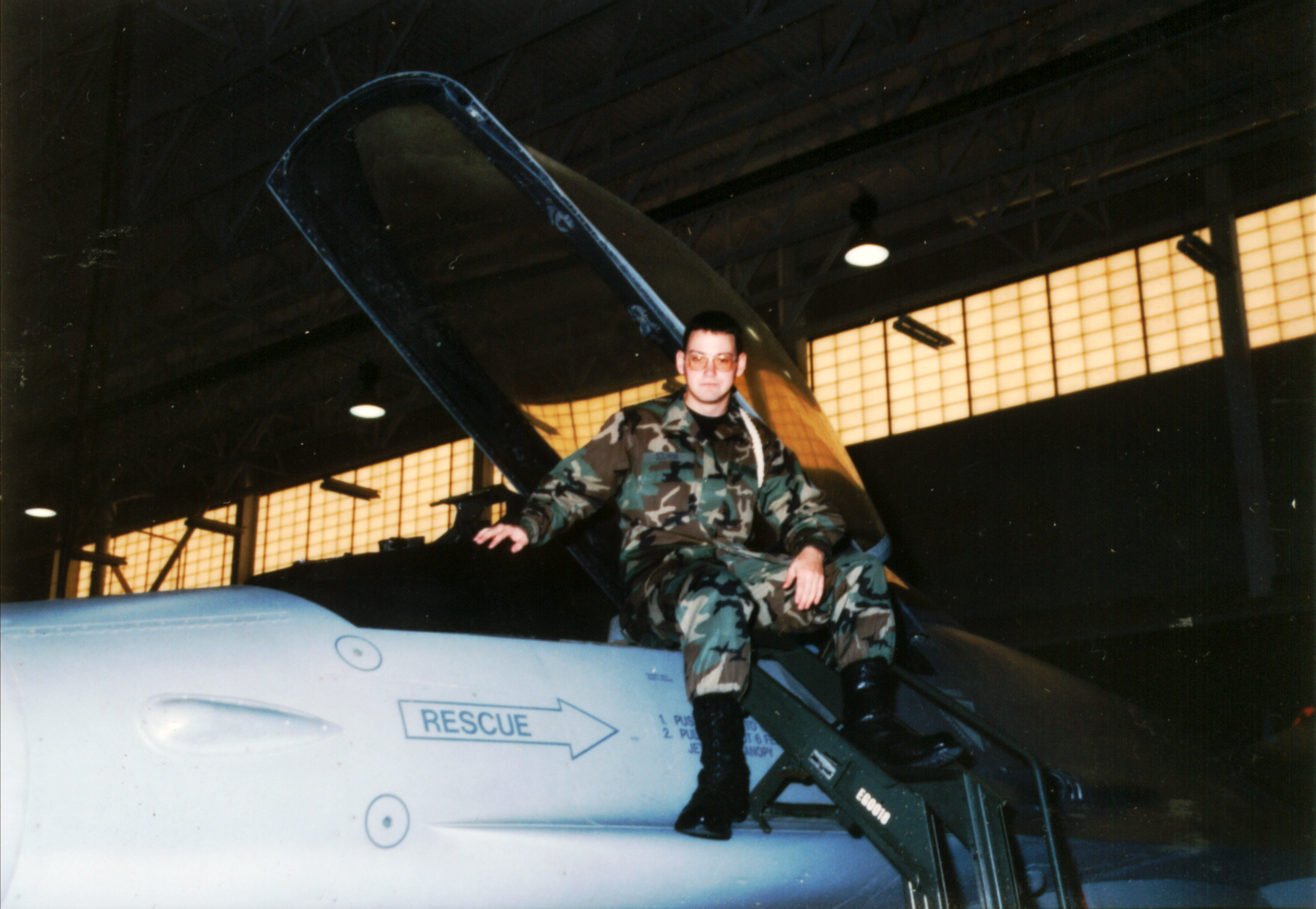
This was the Viper prototype that was not assigned a unit yet so that we
could load something that if it was damaged it would not hurt readiness.
I pulled a stunt years before to become a major general for a week so when
I needed more instruction hours on something I did not know how to fly I
got to pick any air frame on the base. The base commander figured I
wanted to fly the night hawk we had on base. Neither the that nor the air
frame I chose at the time had the specs listed for how fast they went.
So I picked the F-104. I nearly killed myself flying it in a loop de lope at
mach six or seven, basically full throttle all the way through and there
was not a drop of fuel left when I was on the ground. The canopy melted
and frozen solid to the hull. The base commander is yelling at me and
my ears are ringing and the only thing I asked was, So can I fly the F-16
now? He just stared at me and said not a scratch, then he said ah we
can repaint it just don't break the landing gear on that one we don't know
how to repair that one yet. At that point I said I think I am going to sleep...
he said it was not yet lunch time, at which point I passed out from the
blood returning to my head. So I got to fly the prototype but I remember
having to mob the fighter jet after flying it. I had to have the gas mask
inserts welded to the helmet. The helmet felt more like a motor cycle
helmet but flying that was icing on the cake after flying the F-104.
The F-104 was rebuilt from a museum piece by the engine mechanic
training squadron on base lead, which included my friend Merle Paytas.

West Main Turbine Clockwise
East Main Turbine CounterClockwise
WestUp Tri Turbine Clockwise
EastUp Tri Turbine CounterClockwise
EqualUp Tri Turbine Clockwise
DownEqual Mid Turbine Designed to chage the
slipstream flow by spinning couter to Up Turbines
flow or with the flow.
WestDown Clockwise
EastDown CounterClockwise
Sublimination for afterburning but normal
turboprop / hydrofoil concepts are for slower
acceleration and atmospheric travel.
Reversing the turbine's direction in
atmosphere slows it down with out using
a breaking surface, in space it sorta works
by sucking the plume just propelled out,
but gas expelled ahead of the craft and
ignited is the best method I was thinking
about with out worrying about flying through
the propulsion in front of the craft. Much
like the lasers not melting the wings as it
flys through them it is caution area of
design.


Some more diagrams
from Maya.
The files export great
as Stl_ATF files.
from Maya.
The files export great
as Stl_ATF files.

So above is a Draft version of the cladding and any parts exposed to hard vaccum.


ベンジャミンマディアス・ソルハイムがュ彼の肩に竜の男橋脚
The thrust pit works the same way an after burner does. Only it uses super cooled water to spin impellers by using sublimation
to detonate trimex by mixing super cooler Trimex and NOS with heated gases. The gases mix the chamber before the staged or
permanent scafalting holding the turbines in place which spin the gas around the outside of them and through the center using
centripetal force to impact spin like English on a pool cue. with the really hot gas moving as fast as it can and cooling gases
having to move around the outside you get a slip stream effect hitting the empty area behind the turbines exhaust inside the
thrust port. Then the thrust pit flanges sit up against the lip of the cladding so the heated part is not right next to the cladding,
and the heated gas expands out ward to create a mostly cylindrical blast behind it. More side to side than up and down but
controllable by the direction and spin of the exhausting gas. The best method I was able to come up with was cooling glass
coating M48 Alloys to create a smoother surface that is far more heat resistant than the alloy alone. It does mean two to four
inches of quartz or glass. The turbines are exposed to vacuum but they have to be held to dealing with far harsher forces so
I simply keep forgetting that people may not understand that part.


I have to make sure not to put some much up here that companies
can not make money off advancing the parts to go into the design
while explaining the concepts that newton and socrates mostly
understood but had no way to explain better than apples falling
and the motion of the waves. Basically gravity is what people
see, centripetal force is the water evaporating off the ocean and
lifting through convection being thrown towards space in a parabolic
arc upwards then falling back down as the earth has spun past in
the time it travels up and back down again. think of it a vertical
line tapping on a globe as you spin the globe.
I still have to get an SVN setup to allow for a current copy of
the design to be downloaded but the money has to clear and
I have to get info one what is and is not in the design once the
USA Congress figures out what needs to be part of it.
for now there is file up on this site but it is not considered final.

This shows the wider area at the back so that the ruddars can move the full range of motion. You can not see the canopy as
a seperate piece but it is still there it is just flush with the
cladding. Remember this is an Engineering design when you
make changes to it you have to tweak it a little bit to make it
work with the changes you make to it. I might have to build
the Metal frame work to hold the hydrofoil turbines I am using
to export them as STL_ATF files but the spacing was the
more important part of them, well that and mixing super
cooled reactive gas with hot reactive gas, that burns to
create a solid liquid that can be pushed agaisnt but is not
as dangerous as a space junk.